
Introduction #
An inverting amplifier is an operational amplifier configuration in which the input signal is applied to the inverting terminal through a resistor.
The output voltage is an amplified version of the input signal and is inverted in phase by 180°.
This configuration provides precise gain control and is widely used in signal processing and analog conditioning circuits.
Circuit Description #
The inverting amplifier uses a resistive feedback network connected between the output and the inverting input of the operational amplifier.
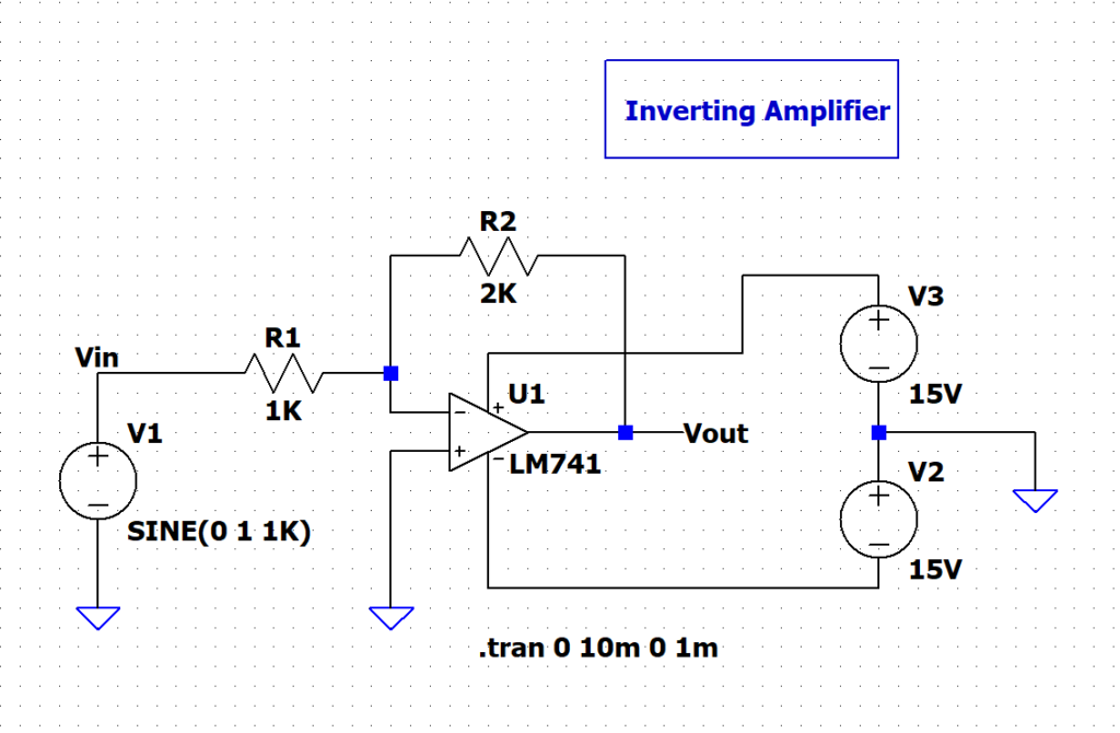
- The input signal is applied to the inverting (−) terminal through an input resistor
- The non-inverting (+) terminal is connected to ground
- A feedback resistor connects the output to the inverting terminal
- Negative feedback controls the closed-loop gain
The input and feedback resistors together determine the gain of the circuit.
Output Waveform Explanation #
The input signal is a sinusoidal waveform applied through the input resistor to the inverting terminal.
The output waveform is also sinusoidal but is inverted with respect to the input signal.
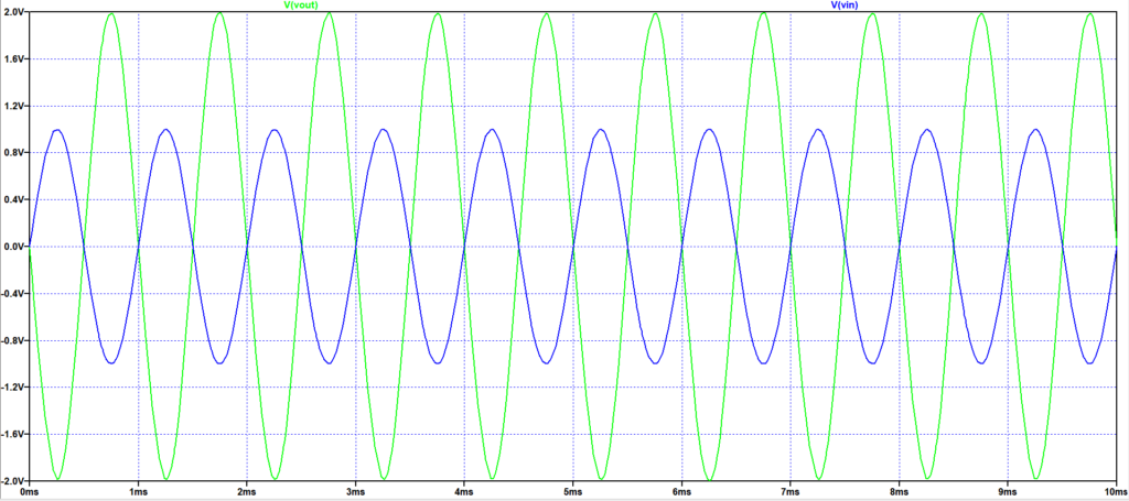
Key observations from the waveform:
- The output amplitude is approximately twice the input amplitude
- The output waveform is phase-shifted by 180° relative to the input
- Input and output signals have the same frequency
- The waveform remains undistorted, indicating linear operation
This confirms correct inverting amplifier behavior and proper negative feedback operation.
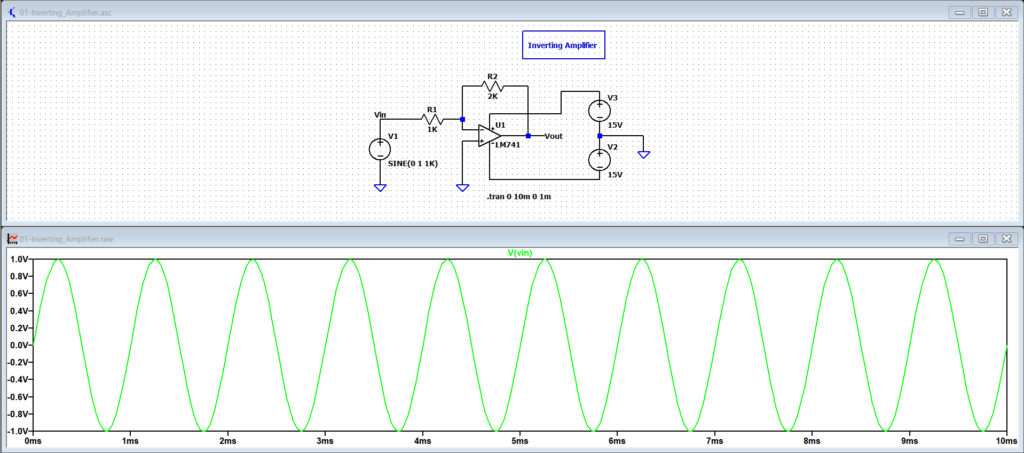
Input and Output Characteristics #
Input:
- Input signal applied to the inverting (−) terminal through a resistor
- Input voltage: sinusoidal signal of ±1 V peak at 1 kHz
- Effective input impedance approximately equal to the input resistor value (1 kΩ)
Supply Voltage:
- Dual power supply operation
- Positive supply: +15 V
- Negative supply: −15 V
- Supply voltages are sufficient to support the required output swing
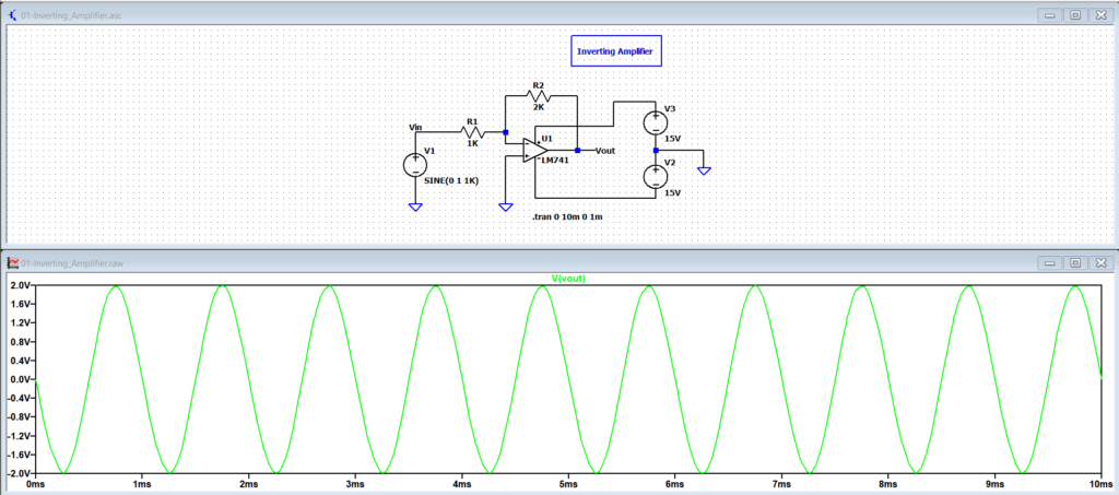
Output:
- Output voltage is an amplified and inverted version of the input signal
- Output peak voltage: approximately ±2 V for a gain of −2
- Output swing limited by the op-amp supply rails and internal output stage
Principle of Operation #
In linear operation, negative feedback causes the op-amp output to adjust such that the voltage at the inverting terminal remains close to ground potential.
As a result:
- The input current through the input resistor flows through the feedback resistor
- The output voltage develops across the feedback resistor
- A fixed relationship is established between input voltage and output voltage
This behavior produces a stable and predictable closed-loop gain.
Gain Equation #
The closed-loop voltage gain of an inverting amplifier is given by:
Gain = −(Rf / Rin)
Where:
- Rf is the feedback resistor connected between output and inverting input
- Rin is the input resistor connected between the input source and the inverting terminal
The negative sign indicates phase inversion.
Gain Calculation and Verification #
Given:
- Rf = 2 kΩ
- Rin = 1 kΩ
Calculated gain:
Gain = −(2 / 1)
Gain = −2
For an input voltage = ±1 V
Expected output voltage = ±2 V (inverted)
The simulated waveform confirms the calculated gain and phase inversion.
Applications #
- Signal amplification with controlled input impedance
- Audio and signal processing circuits
- Summing and weighting amplifiers
- Analog computation and conditioning stages
Practical Notes #
- Input impedance is limited by the input resistor value
- Output saturation occurs if the required output exceeds supply limits
- Gain accuracy depends on resistor tolerance
- Bandwidth decreases as gain magnitude increases


