
Build a Logic AND Gate with BJT Transistor
Overview
Logic gates are the basis of many digital electronics circuits. From the basic Flip-Flops to Microcontroller, logic gates forms the underlying principle for doing arithmetic operations, storing bits etc. The combination of Logic gates can build Flip-Flops, Registers and counters etc. The logic gate itself can be build using combination of discrete components like Resistor, Transistor, Diodes etc. There are many types of logic gates and each of them has different logic and different purpose.
In this project we will build a Logic AND Gate using BJT transistor, understand its operation with the help of truth table and verify its output.
Components Used
To build an OR gate using transistor circuit, you’ll need these readily available components:
| Component | Value | Qty |
|---|---|---|
| NPN Transistor | BC547, 2N2222 or any small signal transistor | 2 |
| Resistor | 4.7 kilo ohm | 2 |
| Resistor | 270 ohm or 330 ohm | 1 |
| LED | Any colour | 1 |
| Push Button | Any size | 2 |
| Power Source | 5V | 1 |
| Jumper Wires | 26 AWG | – |
| Breadboard | – | 1 |
Working Principle
The logic operation of AND Gate is straightforward: the output is High when all inputs are High. If either input A or input B is High, output Y is Low. AND gate has below circuit symbol. The flat end is input and the curved end is output.
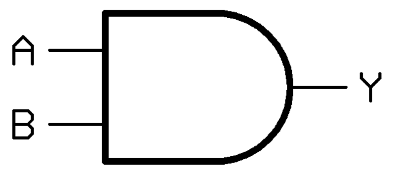
The operation of AND gate can be summarized using the Truth table shown below. This principle can be extended to as many inputs as is needed, the output is true if all of the inputs are true.
| A | B | Y |
|---|---|---|
| 0 | 0 | 0 |
| 0 | 1 | 0 |
| 1 | 0 | 0 |
| 1 | 1 | 1 |
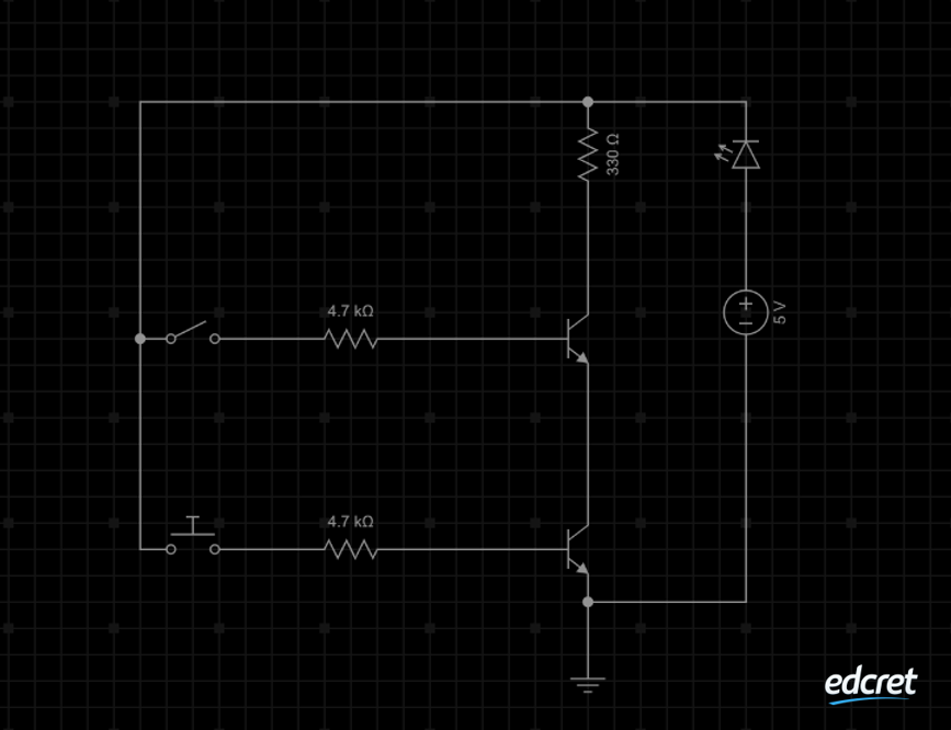
Circuit Connection
Results
Project Files
Code • Circuit • Wiring • Guide
