
Introduction #
A non-inverting amplifier is an operational amplifier configuration in which the input signal is applied directly to the non-inverting terminal of the op-amp.
The output voltage is an amplified replica of the input voltage and remains in phase with it.
This configuration is commonly used in signal-conditioning applications where high input impedance, stable voltage gain, and low signal distortion are required.
Circuit Description #
The non-inverting amplifier uses a resistive feedback network connected between the output terminal and the inverting input of the operational amplifier.
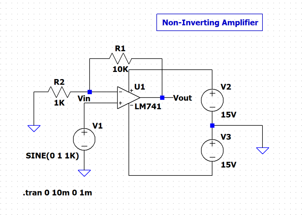
- The input signal is applied to the non-inverting (+) terminal
- The inverting (−) terminal receives a fraction of the output voltage through a voltage divider
- Negative feedback controls the overall gain of the circuit
The feedback network forces the op-amp to operate in its linear region, allowing the gain to be set precisely using external resistors.
Output Waveform Explanation #
The input signal is a sinusoidal waveform applied to the non-inverting terminal.
The output waveform is also sinusoidal and remains in phase with the input signal.
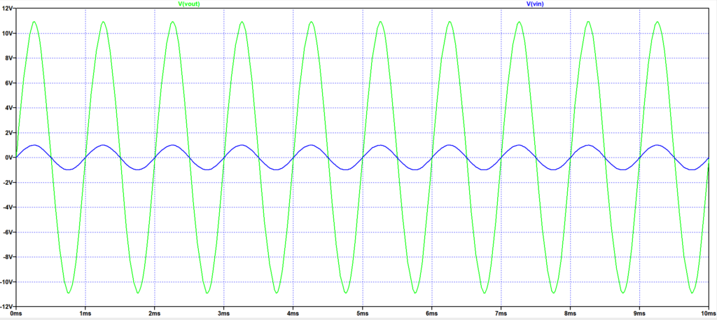
Key observations from the waveform:
- The output amplitude is approximately 11 times the input amplitude
- Both input and output have the same frequency
- No phase inversion is observed
- The waveform remains undistorted, indicating linear operation
This confirms correct non-inverting amplifier behavior and proper negative feedback operation.
Input and Output Characteristics #
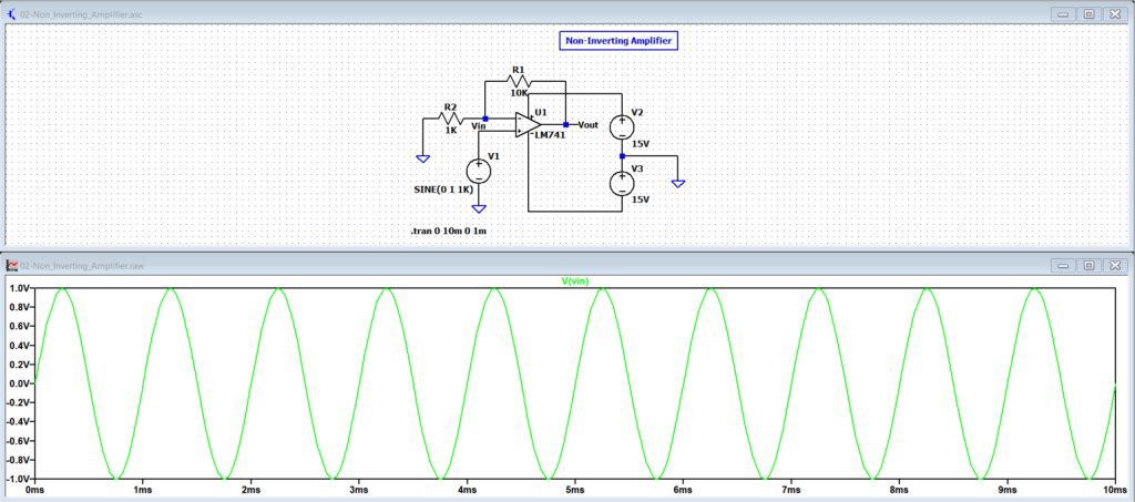
Input:
- Input signal is applied to the non-inverting (+) terminal
- Input voltage: sinusoidal signal of ±1 V peak at 1 kHz
- Very high input impedance of the op-amp
- Input current is negligible, resulting in minimal loading on the signal source
Supply Voltage:
- Dual power supply operation
- Positive supply: +15 V
- Negative supply: −15 V
- Supply voltages are sufficient to support the required output swing without saturation
Output:
- Output voltage is an amplified version of the input signal
- Output remains in phase with the input waveform
- Output peak voltage: approximately ±11 V for a gain of 11
- Output swing is limited by the op-amp supply rails and internal output stage
Principle of Operation #
In linear operation, the op-amp output adjusts itself through negative feedback such that the voltage at the inverting terminal follows the voltage applied at the non-inverting terminal.
This behavior is a consequence of:
- Very high internal gain of the op-amp
- The presence of negative feedback
As a result, the feedback network forces a fixed relationship between the input voltage and the output voltage, producing a stable and predictable closed-loop gain.
(The input terminals are not physically shorted; they are driven to nearly the same voltage by feedback.)
Gain Equation #
The closed-loop voltage gain of a non-inverting amplifier is given by:
Gain = 1 + (Rf / R1)
Where:
- Rf is the feedback resistor connected between the output and the inverting input
- R1 is the resistor connected between the inverting input and ground
This expression shows that the gain depends only on the resistor ratio and is independent of the op-amp’s internal gain.
Gain Calculation and Verification #
Given:
- Rf = 10 kΩ
- R1 = 1 kΩ
Calculated gain:
Gain = 1 + (10 / 1)
Gain = 11
For an input voltage of ±1 V:
Expected output voltage = ±11 V
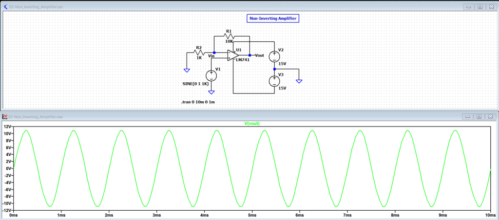
The simulated output waveform confirms this calculated gain, with the output remaining in phase with the input signal.
Applications #
- Voltage amplification with high input impedance
- Sensor and transducer signal conditioning
- Audio and instrumentation pre-amplifiers
- Buffer stages in analog signal chains
Practical Notes #
- Output saturation occurs if the required output voltage exceeds the supply limits
- Gain accuracy depends on resistor tolerance and temperature stability
- Higher gain values reduce the effective bandwidth of the amplifier
- Stability must be considered when operating at higher frequencies


