
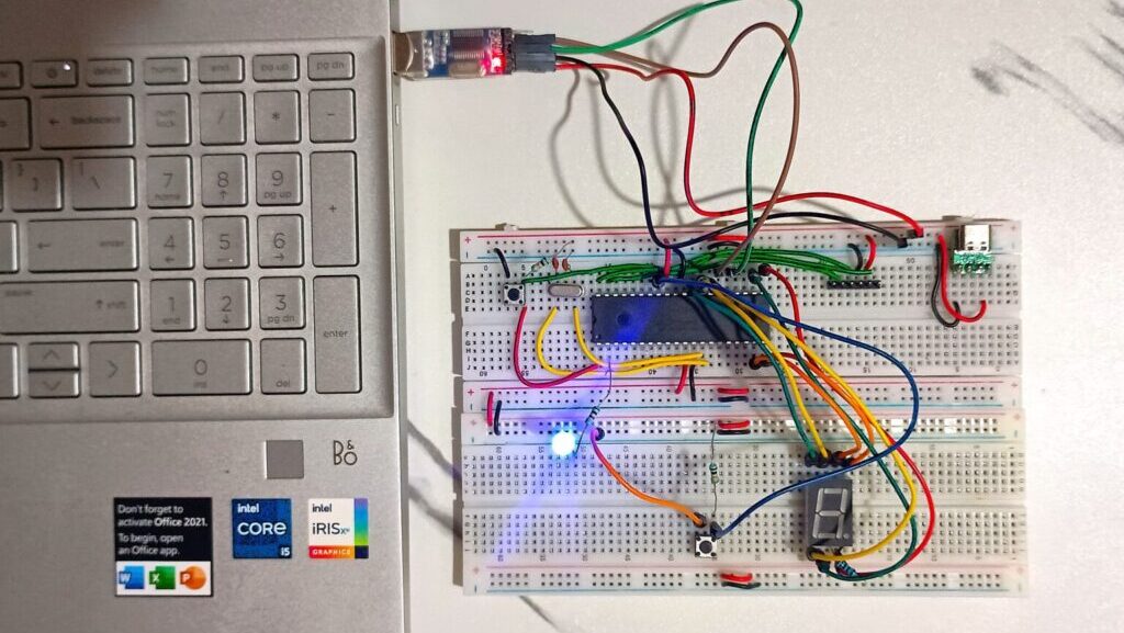
In this post, I will explain how to connect a PIC18F45Q10 microcontroller to a PC terminal using a PL2303 USB to TTL converter.
The idea is simple: blink an LED to confirm the microcontroller is running, and print “Hello World” continuously over UART to the terminal.
Along the way, I also faced a few practical issues, which I have covered here so that anyone following this guide can avoid them.
The hardware connection is straightforward but needs attention to detail:
| PIC18F45Q10 Pin | Connects To | Purpose |
|---|---|---|
| RC6 (TX) | PL2303 RX | Send UART data from PIC to PC |
| RC7 (RX) | PL2303 TX | Receive UART data from PC |
| GND | GND | Common Ground Connection |
| RA0 | LED + 330Ω Resistor to GND | Visual confirmation of microcontroller running |
| VDD, VSS | 5V and GND | Power the PIC properly |
| OSC1/OSC2 | 20MHz Crystal with 22pF capacitors to GND | Clock Source for Stable Operation |
Important points to check:
Initially, my PL2303 module was detected by Windows but did not create a proper COM port.
The root cause was the use of an older PL2303HXA chip which is not supported by newer Windows drivers.
To fix it:
It is also recommended to prevent Windows from automatically updating this driver later.
Here is the complete working code for the setup:
#include <xc.h>
#include <stdint.h>

// Configuration Bits
#pragma config FEXTOSC = HS
#pragma config RSTOSC = EXTOSC
#pragma config CLKOUTEN = OFF
#pragma config CSWEN = ON
#pragma config FCMEN = ON
#pragma config MCLRE = EXTMCLR
#pragma config WDTE = OFF
#pragma config LVP = OFF

#define _XTAL_FREQ 20000000UL

void UART_Init(void)
{
    uint16_t baud_rate_value = (_XTAL_FREQ / (64UL * 9600)) - 1;

    SP1BRGL = (uint8_t)baud_rate_value;
    SP1BRGH = (uint8_t)(baud_rate_value >> 8);

    TRISC6 = 1;
    TRISC7 = 1;

    TX1STAbits.SYNC = 0;
    TX1STAbits.BRGH = 0;
    RC1STAbits.SPEN = 1;
    TX1STAbits.TXEN = 1;
    RC1STAbits.CREN = 1;
}

void UART_Write(char data)
{
    while(!TX1STAbits.TRMT);
    TX1REG = data;
}

void UART_Write_Text(const char* text)
{
    while(*text != '\0')
    {
        UART_Write(*text);
        text++;
    }
}

void main(void)
{
    UART_Init();

    RC6PPS = 0x09; // Map TX to RC6
    RX1PPS = 0x17; // Map RX to RC7

    TRISA0 = 0;    // Set RA0 as output
    LATA0 = 0;     // Initially OFF

    while(1)
    {
        UART_Write_Text("Hello World\r\n");

        LATA0 = 1;
        __delay_ms(500);

        LATA0 = 0;
        __delay_ms(500);
    }
}
Flash this code into the PIC18F45Q10 using MPLAB X IDE and your PIC programmer (PICkit, Snap, or any compatible programmer).
Once the code is flashed:
If everything is connected properly:
This confirms that both your GPIO and UART setups are working perfectly.
Unlike older PICs where UART pins were fixed, PIC18F45Q10 allows routing internal peripherals to different I/O pins through a system called Peripheral Pin Select (PPS).
In this project:
RC6PPS = 0x09; maps UART Transmit (TX1) to RC6.RX1PPS = 0x17; maps UART Receive (RX1) to RC7.This flexibility is highly useful during PCB design and can make hardware routing much easier.
It is worth noting that microcontrollers like STM32 also offer flexible pin functions but are more restricted compared to the complete freedom given by PIC18 PPS.
Always double-check each of these areas if you face any unexpected behavior.
This project might seem simple, but it brings together several important embedded system concepts:
Completing this interface and seeing both the LED blink and UART communication working reliably is a solid confidence boost when working with new microcontrollers.
If you are starting with the PIC18 family, this project gives you a strong foundation to build further applications.

Your information will never be shared with any third party