
In this blog post, we’ll explore how to interface a simple LED with the PIC18F45Q10 microcontroller and make it blink at regular intervals. This is a great beginner project to understand how to work with input/output (I/O) pins, configure the microcontroller, and implement a delay for controlling time-based events.
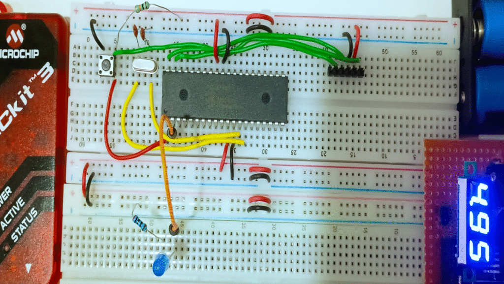
The circuit for interfacing the LED with the PIC18F45Q10 is very simple. We’ll use pin RA0 (pin 2 on the chip) as an output to control the LED. The LED will be connected to this pin with a current-limiting resistor (220Ω).
The anode (positive) of the LED will be connected to RA0, and the cathode (negative) will be connected to the ground.

Here’s the simple circuit diagram:

The following code example demonstrates how to blink an LED using the PIC18F45Q10 microcontroller. We’ll configure the I/O pins, set a delay, and toggle the LED on and off.
/*

 * File:   main.c

 * Author: erraj

 *

 * Created on January 5, 2025, 2:26 PM

 */

#include <xc.h>  // Include the header file for the PIC18F45Q10

// PIC18F45Q10 Configuration Bit Settings

// 'C' source line config statements

// CONFIG1L

#pragma config FEXTOSC = HS    // External Oscillator mode Selection bits (EC (external clock) above 8 MHz; PFM set to high power)

#pragma config RSTOSC = EXTOSC  // Power-up default value for COSC bits (EXTOSC operating per FEXTOSC bits (device manufacturing default))

// CONFIG2L

#pragma config MCLRE = EXTMCLR  // Master Clear Enable bit (MCLR pin (RE3) is MCLR)

// CONFIG3L

#pragma config WDTE = OFF       // WDT operating mode (WDT disabled)

// End of configuration bits

#define _XTAL_FREQ 20000000  // Define crystal frequency (20 MHz)

void main(void) {

    // Set RA0 as output (LED pin)

    TRISA = 0xFF;   // Set PORTA as input (default)

    TRISA0 = 0;     // Set RA0 as output

    // Main loop

    while(1) {

        LATAbits.LATA0 = 1;  // Turn LED ON (RA0 high)

        __delay_ms(500);     // Wait for 1 second

        LATAbits.LATA0 = 0;  // Turn LED OFF (RA0 low)

        __delay_ms(500);     // Wait for 1 second

    }

}
Code Breakdown:
Key Functions:
When the circuit is powered up, the LED connected to RA0 will start blinking with a 1-second interval (500 ms ON, 500 ms OFF). The flashing LED demonstrates how the microcontroller can control I/O pins and implement delays. This basic setup can be expanded to include more LEDs or integrated with sensors to create more complex applications.
Watch the Demo Video:
Click here to view the video demonstration!
This simple project demonstrates how to interface an LED with the PIC18F45Q10 microcontroller and control it using basic I/O operations. By using an external oscillator and configuring the I/O pins, we can toggle the LED on and off with a delay, effectively creating a blinking LED.
This project serves as a great foundation for beginners looking to understand microcontroller programming and hardware interfacing. You can expand this project by connecting multiple LEDs, adding sensors, or implementing more advanced control mechanisms.
If you have any questions or want to explore more advanced topics, feel free to leave a comment below. Happy coding!

Your information will never be shared with any third party